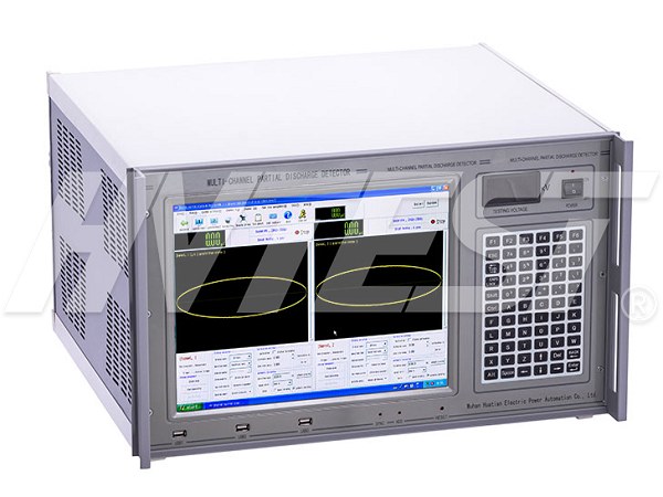
Partial discharge testing can help identify developing insulation issues in electrical equipment. Because the work involves test samples, energized equipment, measuring instruments, and sensitive connections, a disciplined setup process is essential. The following partial discharge detection system safety practices summarize key points for preparing the instrument, controlling interference, making connections, and completing calibration before a test.
Start with grounding and a controlled work area
Grounding is the first priority before any connection work begins. Ground the instrument’s grounding terminal before connecting other parts of the test arrangement. The grounding terminal of the detection impedance also needs a reliable ground connection. This helps reduce the risk of high voltage being introduced where it is not expected and supports a more stable measurement environment.
Plan the physical layout before applying test voltage. Where conditions permit, place the test sample inside a shielded room while locating the pressurizing equipment and measuring instrument outside the room. This arrangement can reduce interference reaching the detection system.
Distance also matters. The instrument should be positioned at least 7 meters from the test sample. If baseline interference remains high, a metal-mesh protective fence between the instrument and sample may provide additional separation. Keep the connection between the test impedance and the sample as short as practical, since unnecessarily long connections can increase susceptibility to interference.
Prepare the instrument before testing
After the instrument has been connected, allow a warm-up period of no less than five minutes before the test. This step should be incorporated into the testing routine rather than skipped to save time.
Protect the instrument from conditions that may affect its use or condition. It should be kept away from corrosive exposure, direct sunlight, and strong magnetic sources during testing. Strong vibration should also be avoided. When the instrument is transported, suitable anti-vibration measures are important.
Operators should understand each interface before using it. For example, the keyboard interface uses an RJ-45-style connection. It can be inserted directly, but the plastic retaining tab must be pressed when removing it. Careful connector handling helps avoid damage to the interface and prevents an interruption during setup.
Manage powered connections carefully
Do not insert or remove plug-in interfaces while the instrument is powered. Before performing a plug-in interface operation, turn off the instrument using its switch. This simple control is particularly important around a partial discharge detection system because the overall test arrangement may involve high voltage and sensitive measurement components.
Detection impedance selection should match the capacitance of the test product. The applicable selection method should be taken from the relevant instrument instructions. A suitable impedance choice and short connection path support a more controlled test setup without assuming that one configuration fits every sample.
Use the zero-scale input and phase reference with care
Some setups use the zero-scale input to provide an external zero-scale signal derived from the test power supply through a voltage divider. The input voltage for the zero-scale unit must remain within the instrument’s specified range. Do not exceed the stated input limitation.
When the test power supply and instrument supply are in the same phase, or when the test power supply is strictly synchronized with power frequency, the instrument’s zero mark may be used. In either case, the phase should be calibrated. Confirming the reference condition before measurement helps make the displayed phase information meaningful for the specific test arrangement.
Complete calibration, then remove the calibrator
Calibration should be completed before the high-voltage test proceeds. Once calibration is finished, disconnect the calibration square wave to prevent high-voltage breakdown during the test. Turn off the relevant power switch after calibration as required by the operating procedure.
The calibration square wave device uses a rechargeable battery. When it has no power, its red light turns off and the square-wave output may no longer be accurate. Charge the calibrator when it is not powered. The source guidance indicates a typical charging period of 10 to 12 hours and advises against unnecessarily long charging. It also notes that the square wave may be intentionally turned on to discharge before recharging when a full charge is needed.
Maintain safe testing discipline
Before operating a partial discharge detection system, personnel should be familiar with the safety instructions and the specific operating instructions for the equipment in use. A sound process includes grounding first, allowing warm-up time, minimizing interference, keeping safe separation, avoiding live plug-in operations, selecting the detection impedance appropriately, and disconnecting calibration equipment before high-voltage testing. These practices help protect personnel, equipment, and the integrity of the test process.