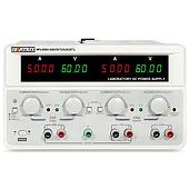
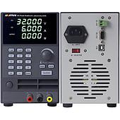
The battery is one of the most important components of an electric-assisted bicycle. However, evaluating the performance of the entire system requires more than simply checking the battery pack’s voltage or capacity. The BMS, controller, and protection circuits also need to be tested under different conditions, ranging from normal operation to over-discharge, overload, and short-circuit conditions.
One testing approach is to combine a battery cell simulator, programmable DC power supply, and electronic load. Each device performs a specific role in the testing process, allowing technicians to create controlled test conditions and monitor the system’s response.
Testing with a Battery Cell Simulator
Evaluating the system’s response to changes in individual cell conditions
The BMS is responsible for monitoring the condition of individual cells, controlling the charging and discharging process, and activating protection functions when abnormal conditions are detected.
A battery cell simulator can reproduce electrical conditions corresponding to individual battery cells without requiring actual cells to be used in every test. Technicians can set battery parameters such as voltage, state of charge, depth of discharge, open-circuit voltage, and internal resistance to evaluate the response of the BMS and controller. Instead of waiting for a real battery pack to reach the required test condition, the desired conditions can be configured directly on the simulator.
Measuring BMS standby current
Even when the bicycle is not operating, the BMS still needs to maintain certain monitoring and protection functions and therefore continues to consume power. Excessive standby current can affect the battery pack’s ability to retain energy during storage.
Measuring quiescent current helps determine the actual power consumption of the BMS. For microamp-level measurements, an instrument with suitable current resolution can detect very small levels of consumption and provide a more accurate assessment of the system’s standby state.
Monitoring rapid changes
During testing, voltage and current can change rapidly when the BMS switches between operating states or activates a protection function. Therefore, in addition to steady-state values, data recorded during state transitions should also be captured.
A battery cell simulator with an appropriate sampling rate can monitor both the stabilization process and rapid changes, making it easier to identify abnormal BMS responses.
Testing Battery Charging with a Programmable DC Power Supply
A high-voltage programmable DC power supply is used to provide voltage and current according to predefined test conditions. Precise control of the input parameters allows technicians to evaluate the response of the battery, BMS, and protection circuits as charging conditions change.
In addition to testing under rated conditions, a programmable DC power supply can generate different test scenarios to evaluate the system’s ability to detect and handle abnormal conditions.
Testing abnormal charging conditions
A BMS must be able to detect voltage or current levels that exceed the permitted limits and respond appropriately.
During the test, the DC power supply can be configured to apply specific voltage and current levels or a predefined sequence of changes. Technicians monitor when the BMS detects the abnormal condition, how the system responds, and the status of the protection circuit after the fault has been handled.
These tests must be configured according to the safety limits of the battery pack and test equipment, particularly when the test conditions could potentially damage the cells.
Evaluating battery capacity
A DC power supply can also be used in controlled charging cycles to evaluate battery capacity and changes in battery performance over multiple cycles.
By combining charging and discharging data, technicians can determine the actual battery capacity, compare it with the rated value, and monitor battery degradation throughout the testing process.
Testing with an Electronic Load
Creating a controlled load during discharge
Actively controlling the load allows technicians to monitor voltage, current, and other relevant parameters throughout the discharge process instead of relying on the actual load of the bicycle.
Testing over-discharge
Over-discharge is one of the conditions that should be considered when evaluating battery protection systems. Continued discharge below the permitted limit can cause cell voltage to fall to a dangerous level and may affect battery life.
A DC electronic load can create a predefined discharge condition to determine when the BMS detects low voltage and activates its protection function. The test results indicate whether the system responds correctly to the designed protection threshold.
Testing external short circuits
An external short circuit can cause the current to rise very rapidly, creating a risk of excessive heat generation and compromising battery pack safety. The purpose of this test is to evaluate the fault detection capability and response of the protection circuit.
During the test, current and temperature should be monitored to determine whether the system can interrupt the circuit and how quickly it responds to the fault.
This is a high-risk test and must therefore be performed under strictly controlled conditions, with appropriate protective equipment and safety procedures in place.
Developing a Battery Testing Procedure
When the equipment is combined according to its specific functions, the testing process can be carried out in the following sequence:
Cell state simulation → BMS testing → Charging test → Discharge test → Protection function evaluation.
The cell simulator focuses on generating different electrical states to test the BMS and controller. The programmable DC power supply provides controlled power and charging conditions. The electronic load creates a controlled load during discharge and supports tests under predefined conditions.
This approach reduces the need to prepare multiple battery packs for different test scenarios. More importantly, technicians can independently adjust individual parameters, record the system’s response, and compare results across different tests.
For electric-assisted bicycle batteries, test equipment should be selected based on the battery pack’s voltage, current, power, and the conditions that need to be evaluated. Tests involving over-discharge, overload, or short circuits must also be designed according to the specific safety limits of each battery type.
With an appropriate testing procedure, a battery cell simulator combined with a programmable DC power supply and electronic load can support the evaluation of the BMS, controller, and protection system during the research and development stage, before moving on to tests using complete battery packs.