When engineers calculate a tolerance stack, every dimension is based on the original measurement system. Converting dimensions to another system and rounding the values introduces small errors at each dimension. Although each error may be only a few micrometers, they can accumulate across multiple mating surfaces, causing the final clearance to deviate from the original design intent.
Feeler Gauge: Why Is It Important to Use the Correct Measurement System?
A feeler gage
itself does not determine measurement accuracy. The engineering drawing specifies which measurement system should be used.
Machinery designed in the United States is typically dimensioned and toleranced in inches, while European equipment is generally designed using the metric system.
For example, a clearance specified as 0.003 in is not exactly equivalent to 0.08 mm, even though the difference is only a few micrometers. Therefore, the standard conversion of 1 inch = 25.4 mm is suitable for general measurements but may not be appropriate for applications requiring high precision.
When engineers calculate tolerance stacks, every dimension follows the original design measurement system. Converting dimensions and rounding them can introduce small errors throughout precision engines, molds, or other equipment with tight tolerances. Each individual deviation may be only a few micrometers, but once accumulated across multiple mating surfaces, the resulting clearance may no longer match the original design specification.
Does a Difference of a Few Micrometers Matter ?
For many routine maintenance tasks, the answer is no.
However, in high-precision mechanisms, a difference of only a few micrometers can be enough to affect alignment accuracy.
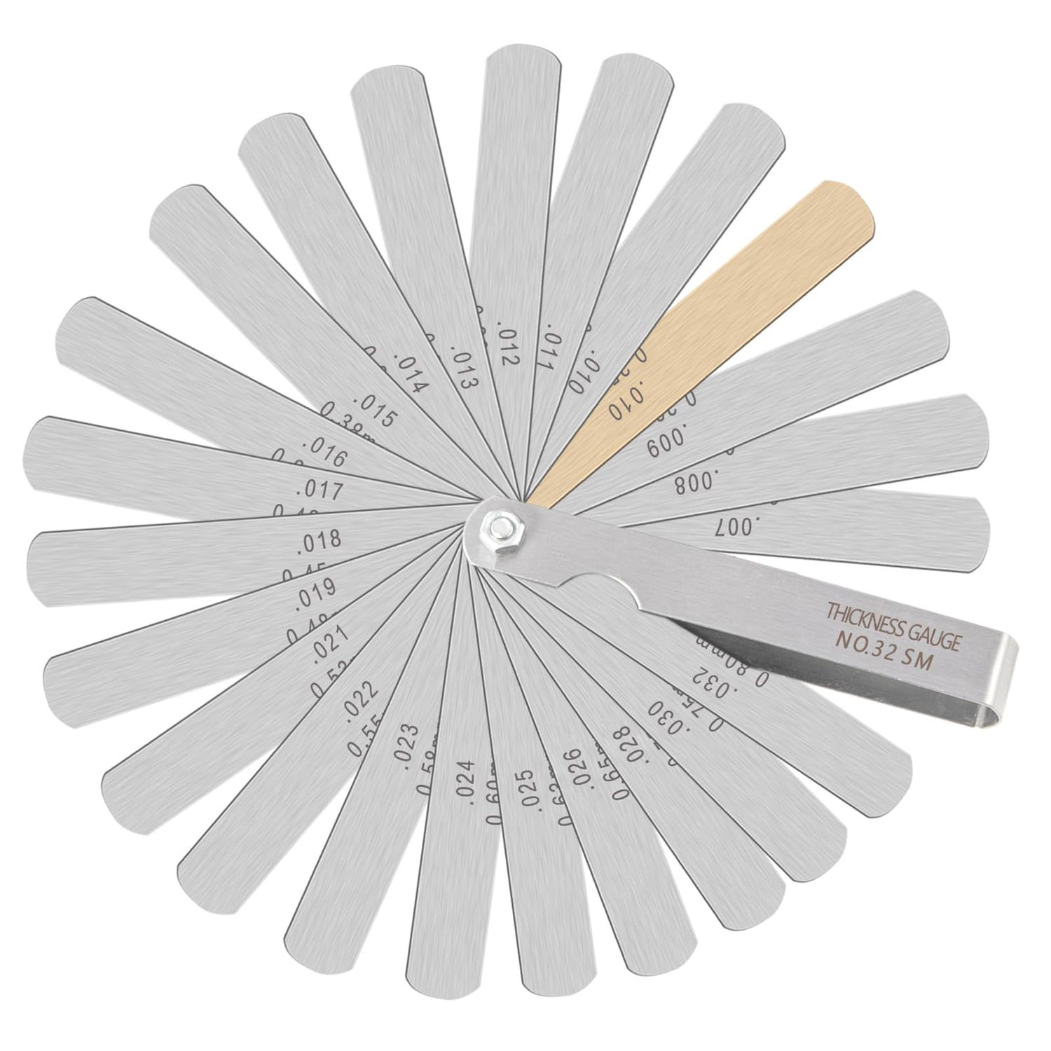
For example, a 0.003-inch taper gage blade has an actual thickness of 0.0762 mm.
Replacing it with a 0.08 mm blade creates a difference of approximately 3.8 μm. Although this deviation is almost impossible to see with the naked eye, it already exceeds the allowable tolerance of many precision applications, such as high-speed bearings, stamping dies, and certain transmission assemblies.
What engineers are concerned about is not the absolute numerical difference but whether the component still remains within its specified design tolerance.
The Difference Can Also Be Felt During Measurement
Another factor is the feel of pulling the blade through the clearance.
When multiple feeler gauge blades are stacked together, a thin film of oil remains between the blades, creating additional contact surfaces. As a result, the friction differs from that of a single blade having the same combined thickness. For adjustments that rely on the drag felt while pulling the blade, this difference can sometimes lead two technicians to obtain different results even when using the same nominal thickness.
This is one reason why many manufacturers continue to produce single blades in commonly used thicknesses instead of recommending that users always combine multiple blades.
Why Do Many Feeler Gauge Sets Include Both Metric and Inch Blades ?
If the purpose were simply unit conversion, manufacturers would not need to produce separate metric and inch feeler gauge sets.
The existence of both systems reflects the practical requirements of mechanical engineering. Equipment designed using one measurement system should generally be inspected, maintained, and calibrated using that same system to avoid errors introduced during unit conversion.
For workshops servicing both European and American machinery, having both metric and inch thickness feeler gage
sets is often essential.
The most significant difference between the two measurement systems is not the unit itself, but preserving the original design intent of the engineering drawing. For this reason, precision machine shops typically select feeler gauges that match the measurement system specified for the equipment from the outset.