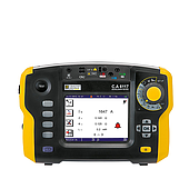
Consequently, the MRI installation area typically requires measurements to be taken both before and after completion. The resulting data facilitates the detection of interference sources, the assessment of performance parameters, the monitoring of temperature fluctuations, the recording of power quality, and the determination of the system's operational status.
Why must the area where the MRI machine is located be shielded against electromagnetic interference?
MRI systems generate and acquire highly sensitive radio signals. Sources of interference such as high-power motors, electrical substations, elevators, broadcasting systems, or nearby electrical equipment can cause signal interference or create artifacts in clinical images.
A metal enclosure surrounding the scanner room, commonly known as a Faraday cage, prevents external radio-frequency interference from entering or leaking into the space. Shielding effectiveness depends on the materials, construction, joints, and any points where the metal barrier is penetrated.
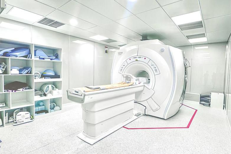
Access doors, observation windows, cable conduits, piping, and ventilation systems must all be treated in accordance with the shielding design. A single substandard connection point can create a path for signal leakage, even if the surrounding surfaces have been properly constructed.
How is RF shielding effectiveness measured?
Engineers can transmit a known RF signal from outside the shielding and then measure the signal level remaining inside. The difference between the transmitted and received signals indicates the system's signal attenuation capability across various frequency bands.
A spectrum analyzer is used to observe signals in the frequency domain, detect sources of interference, and evaluate the signal received after passing through the shielding. An RF signal generator produces a signal with a specific frequency and power level for the measurement.
Measurements typically cover multiple locations rather than focusing solely on the center area. This approach helps identify areas with poor shielding effectiveness, particularly around doors, windows, and cable entry points.
Why do doors, windows, and cable penetrations need to be measured separately?
Large metal surfaces generally do not pose the greatest challenge for shielding systems. Instead, moving structures, interface gaps, or connection points between components create more complex treatment requirements.
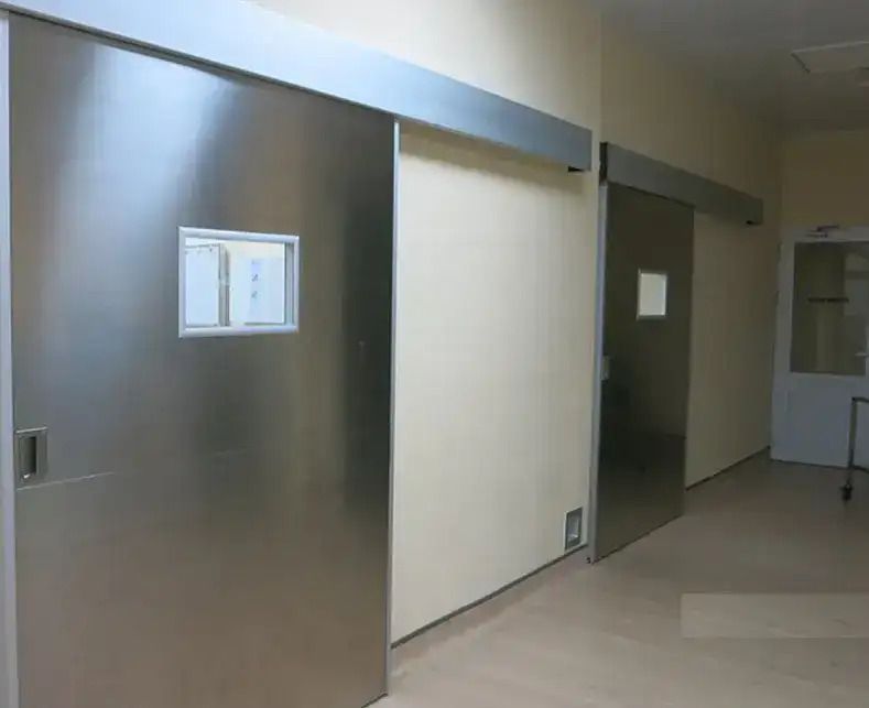
Access doors must maintain proper contact when closed. Observation windows require materials capable of RF shielding. Cable runs, conduits, and ventilation systems necessitate penetration solutions that minimize potential leakage paths.
Measurements taken at multiple locations enable engineers to isolate the cause more quickly if signal attenuation results fail to meet technical specifications.
How should temperature and humidity be monitored?
The temperature and humidity levels to be maintained depend on the specific MRI model, the design of the air conditioning system, and the manufacturer's technical specifications. Therefore, a single, fixed temperature or humidity setting should not be applied to every facility.
A measurement taken at the time of system acceptance reflects environmental conditions only at that specific moment. Temperature and humidity levels can fluctuate over time due to variations in the air conditioning system's load or the operational schedule of the surrounding areas.
Temperature and humidity data loggers enable continuous monitoring over periods ranging from hours to days. Time-series data can reveal temperature spikes during certain times of the day, abnormal humidity fluctuations, or the air conditioning system's failure to maintain the stability required by its design.
Does the power supply quality need to be assessed before connecting the MRI machine?
MRI systems utilize numerous sensitive electronic components and can generate significant load fluctuations during operation. Voltage sags, swells, fluctuations, phase imbalances, and harmonics must all be monitored in accordance with the system's technical specifications.
A power quality analyzer can track voltage, current, frequency, harmonics, and grid anomalies over time. Instead of merely measuring voltage at a single instant, engineers can observe power supply behavior throughout the entire assessment period.
Measurements taken prior to connecting the MRI system help establish the baseline status of the existing power supply. Once the system is operational, subsequent measurements can be compared against these initial results.
What device is needed to measure the grounding for an MRI system?
The grounding system serves both electrical safety and interference control purposes. The measurement method selected must be based on the system structure, design documentation, and the project's technical requirements.
Engineers typically use specialized earth resistance testers employing the 3-pole or 4-pole method to accurately determine resistance values. In confined spaces where driving auxiliary stakes is not feasible, an earth resistance clamp meter serves as a highly suitable alternative. For new projects, soil resistivity measurements can also provide data to inform the design of the grounding system.
Results should not be evaluated in isolation from the conductor configuration, equipotential bonding, and the electrical system as a whole. A compliant grounding system must be assessed against the specific criteria established in the project's technical documentation.
Is the MRI area required to meet cleanroom standards?
Air cleanliness levels depend on the design and intended use of each facility; areas housing MRI machines do not automatically require the same cleanroom classification.
For projects requiring control of airborne particle concentrations, an airborne particle counter may be used to record particle counts by size. The measurement results assist in evaluating air quality and the effectiveness of the filtration system.
The same particle counter can be used for multiple areas, provided that the measurement method, particle sizes, and evaluation limits comply with the standards adopted by the project.
Which measuring instruments are required for each category?
Preparing the list of equipment depends entirely on the measurement scope and technical specifications of each project. Rather than applying a standardized equipment set to every site, engineers typically rely on MRI manufacturer standards to precisely select solutions such as spectrum analyzers and RF signal generators for Faraday cage testing, temperature and humidity data loggers, power quality analyzers, earth resistance testers, and particle counters.
We hope this article helps you better visualize the necessary measurement parameters when preparing an MRI installation site. To ensure accuracy and compliance with specific manufacturer requirements, EMIN is ready to provide expert consultation and supply a comprehensive, optimal set of measurement equipment tailored to each aspect of your project.