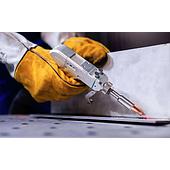
Weld defects are discontinuities or shape problems that can reduce a welded joint’s strength, load-carrying ability, or service safety. Common examples include incomplete penetration, cracks, porosity, slag inclusions, undercut, and weld overflow.
Through an ultrasonic flaw detector, weld defects can identify the correct type of defect, helping the operator review the cause, adjust the process and re-check the connection after repair when necessary.
Summary: Incomplete penetration results from insufficient fusion. Cracks may grow under service loads and require careful inspection. Clean, dry materials help prevent porosity and slag inclusions. Welding parameters and technique strongly affect undercut, overflow, and weld shape.
What is incomplete penetration in a weld?
Incomplete penetration occurs when deposited weld metal does not fully fuse with the base metal or between weld passes. It can appear at weld corners, edges, or between layers in multi-pass welding, reducing the designed cross-section and creating areas of stress concentration.
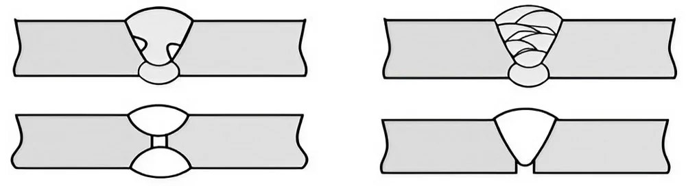
Likely contributors include inadequate joint bevel or root opening, welding current that is too low, excessive travel speed, unsuitable electrode angle, an unsuitable arc length, or uneven electrode movement. Cleaning rust, oil, and other contaminants from the joint and selecting joint preparation suited to the workpiece thickness can help improve fusion.
Where heat input is insufficient, increasing welding current appropriately and reducing travel speed may allow the weld metal to melt and fuse more completely. These adjustments should remain consistent with the applicable welding procedure and joint requirements.
Why are weld cracks a critical defect?
Weld cracks are critical because they can extend over time and reduce a joint’s load-carrying capability. Under static or dynamic loading, a crack can contribute to damage or failure of a welded structure.
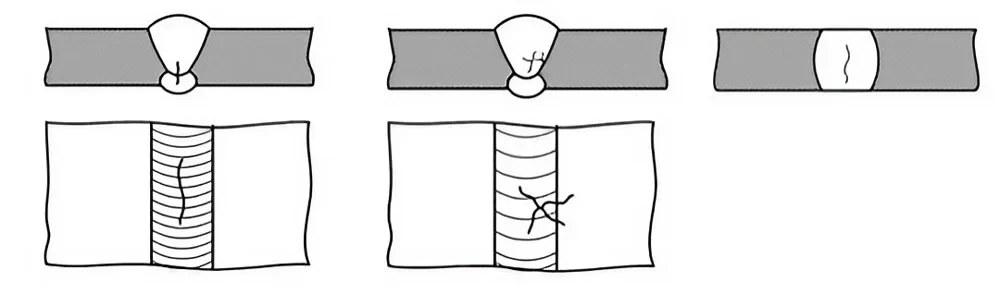
Hot cracks form during weld-metal solidification while the weld is at a temperature above 1000°C. Cold cracks form after welding at temperatures below 1000°C and may not become apparent until hours or days later.
| Crack type or condition | Possible contributing factors | Approaches identified in the source |
|---|---|---|
| Longitudinal crack | Unsuitable welding material, high residual stress, rapid cooling, or unsuitable joint design | Use suitable material, reduce restraint, use preheating or heat retention, and arrange joints appropriately |
| Arc-start or arc-stop crack | A depressed end crater with contaminants or insufficient arc protection | Use equipment with suitable start/stop control or a run-on/run-off tab |
| Transverse crack | Unsuitable welding material, rapid cooling, or an undersized weld | Select suitable material, adjust current and electrode size, and preheat where applicable |
Larger cracks may be found visually or with magnification. Fine or internal cracks may require non-destructive examination methods such as ultrasonic testing, magnetic testing, or radiographic examination.
What causes weld porosity and slag inclusions?
Porosity forms when gas does not escape from molten metal before it solidifies, leaving voids within or on the weld. Slag inclusion occurs when slag or other contaminants remain trapped in the weld metal, at the base-metal boundary, or between weld passes.
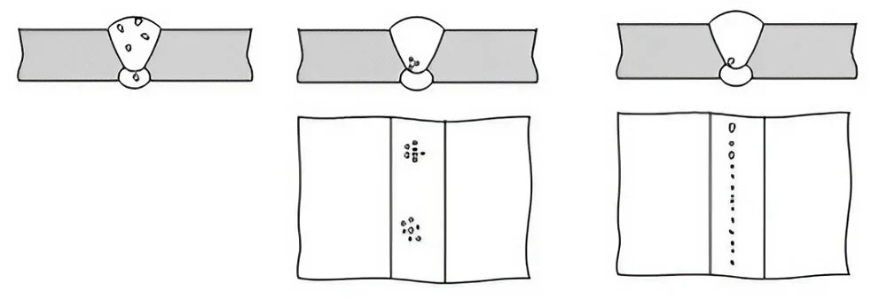
Porosity may be associated with damp filler material, dirty or wet workpiece surfaces, excessive arc length, high travel speed, or an unreliable shielding-gas system for gas-shielded welding. The source also identifies high carbon content in the base or filler material as a possible factor.
Slag inclusion can result from low current, unclean joint edges, failure to remove slag between tack welds or passes, an unsuitable welding angle, excessive travel speed, or rapid cooling. Both conditions can reduce weld strength; slag inclusion can also reduce impact toughness and ductility.
- Clean the workpiece before welding and remove slag between passes.
- Keep filler materials dry and dry them before use when needed.
- Maintain a short, stable arc and adjust travel speed as required.
- For gas-shielded processes, maintain a clean, stable shielding-gas supply at a suitable flow rate.
How do undercut and weld overflow differ?
Undercut is a groove melted into the base metal along the boundary with the deposited weld metal. Weld overflow is molten weld metal flowing beyond the intended joint area instead of remaining concentrated in the weld groove.
Undercut reduces the effective section of the joint and can create stress concentration at the weld edge. It is associated with excessive current, a long arc, unsuitable electrode angle or manipulation, an electrode that is too large for the workpiece thickness, and excessive travel speed.
Weld overflow is associated with excessive current, unsuitable electrode angle, an unsuitable welding position or workpiece orientation, and travel that is too slow. It can distort the weld profile and create localized stress concentration.
| Defect | Primary appearance | Prevention focus |
|---|---|---|
| Undercut | Groove at the weld edge | Use suitable current and electrode size, maintain a short arc, control angle, and allow sufficient fill time |
| Weld overflow | Molten metal spreads outside the intended weld area | Use suitable current, correct electrode angle and welding position, and avoid overly slow travel |
What weld shape defects may also require attention?
Weld shape defects are deviations of the external weld profile from the intended technical or design requirement. They may affect appearance and can create stress concentration that reduces long-term durability.
Contributing factors can include unsuitable fit-up or edge preparation, unstable welding conditions, unsuitable filler material, or incorrect technique. Overheating is described as a result of unsuitable welding conditions that produce a coarse grain structure in deposited metal and the heat-affected zone, reducing mechanical properties.
Spatter is molten metal that is expelled and adheres to the workpiece surface. The source identifies unsuitable welding material and inadequate or incorrect shielding gas as potential causes; spatter also increases cleaning time.
How should identified weld defects be addressed?
Defect handling depends on the defect’s severity and the technical requirements of the structure. For important joints, particularly those subject to high or dynamic loads, the source states that defects should not remain in the joint.
A general repair approach is to remove the defective metal completely, reweld the area, and inspect the repair using suitable methods. For cracks, the source describes drilling at both crack ends to limit propagation, completely removing the cracked region, use a mechanical welding machine to carry out repairs.
Note: The source describes heat treatment as a possible response to overheating defects to improve the weld and heat-affected-zone structure. Repair and inspection decisions should match the applicable technical requirements for the welded structure.