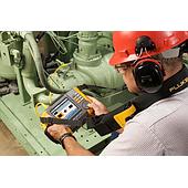
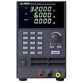
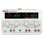
A circuit resistance tester is used to assess resistance in electrical circuits and connection paths. In power-related equipment, resistance at contacts, conductors, and joints can affect energy loss and heating. Testing provides a measured value that can be reviewed against the equipment’s technical requirements, applicable standards, or comparable historical results.
This type of measurement is relevant to maintenance and inspection work because small changes in resistance can indicate a developing connection issue. The result should always be interpreted in the context of the specific equipment, its condition, and the procedure being followed.
What is a circuit resistance tester ?
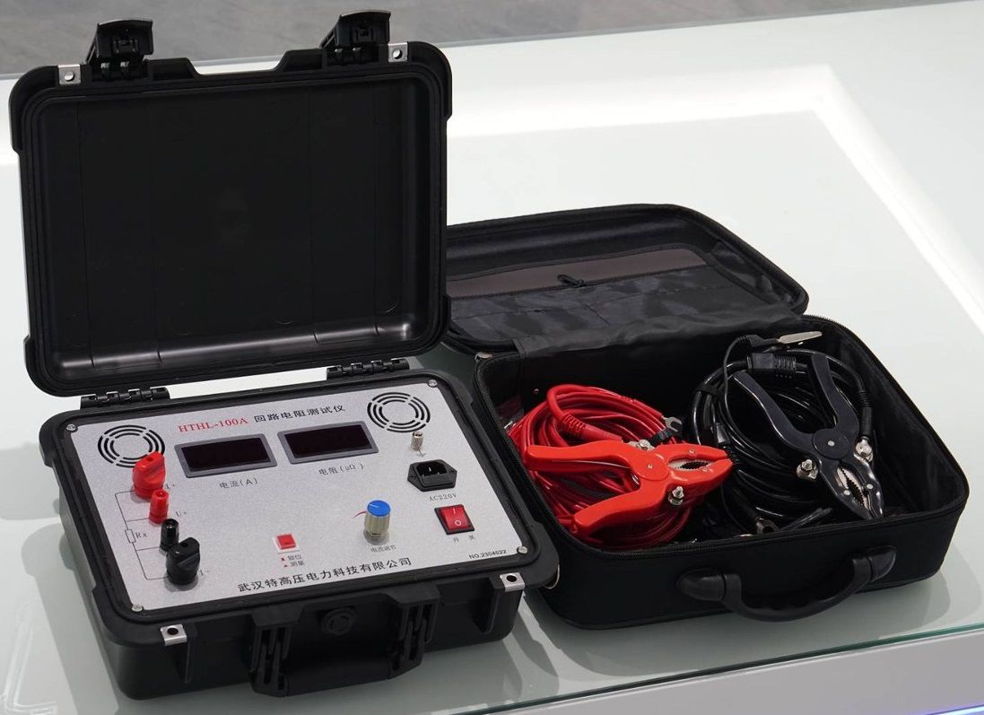
A circuit resistance tester is an instrument designed to measure resistance in an electrical circuit. The measurement approach described for this equipment applies a constant DC current and measures the resulting voltage drop. Using Ohm’s law, expressed as R = U/I, the instrument calculates the resistance value.
DC is used for this measurement because it helps avoid the influence of inductive reactance associated with AC current, allowing the test to focus on the circuit’s resistance characteristic. Depending on the test point, the reading may represent the resistance of a contact, a connection, or a section of the conductive path.
Why circuit resistance measurement matters
Resistance tester opposes current flow. When resistance increases at a conductive path or connection, energy loss and heating may also increase. Over time, an abnormal resistance condition may contribute to equipment damage or a safety concern.
For this reason, circuit resistance tester is commonly considered when inspecting electrical equipment and critical interconnections. It can support condition assessment by identifying readings that differ from expected technical values or from prior measurements taken under comparable conditions.
Factors that can affect resistance readings
Understanding the influences on resistance helps users select suitable test points and evaluate results more carefully. Important factors include the following:
- Conductor material: Copper has lower resistance than aluminum.
- Conductor cross-sectional area: A larger cross-sectional area generally corresponds to lower resistance.
- Connection quality: Oxidation, corrosion, or loose connections can significantly increase contact resistance.
- Temperature: For most conductors, resistance increases as temperature rises.
- Connection length: A longer conductor path has greater total resistance.
These factors also show why readings should not be assessed in isolation. A change in temperature, a different test location, or a modified connection condition can affect comparison with earlier data.
How to evaluate a result
A reading alone does not determine whether a circuit is acceptable. The measured value should be compared with the applicable technical requirements for the micro ohm meter, national or other relevant standards, or previous records from comparable equipment and conditions.
If a value exceeds an allowable range or differs materially from comparable historical results, further inspection may be needed. Possible causes include oxidation, corrosion, loose connectors, insufficient conductor cross-sectional area, or an overly long conductive path. Confirming the cause requires an appropriate inspection of the specific circuit and connection points.
A circuit resistance tester supports electrical quality control by measuring resistance at circuit paths and contacts using a DC-current method.