Relay protection devices monitor electrical systems for abnormal conditions and initiate protective actions when required. Because their operation is central to dependable power-system operation, they need structured checks throughout their service life. A relay protection tester is the instrument used to provide controlled test signals, observe relay responses, and document the results.
Rather than treating testing as a simple pass-or-fail activity, a well-planned process helps teams understand whether a protection device responds at the expected point, in the expected sequence, and under the intended test conditions. This is useful for acceptance work, pre-operation checks, periodic maintenance, and investigations following unexpected results.
What is a microcomputer relay protection tester?
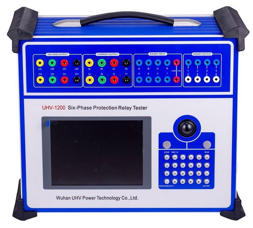
A microcomputer relay protection tester is a professional instrument for evaluating the function, performance, and response accuracy of relay protection devices. It can simulate selected electrical-system conditions by producing signals such as voltage, current, and frequency. The tested relay receives these inputs, while the operator monitors and records its response.
Test conditions may represent normal operation as well as abnormal scenarios, including short-circuit or overload conditions. The purpose is to compare the relay’s observed behavior with the requirements of the selected test plan. This comparison can help identify an incorrect response, an unexpected operating sequence, or a condition that requires further review.
Why test quality depends on more than the relay
Reliable conclusions depend on the full testing setup, not only on the device under test. Careful control of several factors improves the usefulness of a test record.
Signal accuracy
The accuracy of output voltage, current, and frequency affects the actual input applied to the protection relay. If the applied signal differs from the intended value, the observed response may not represent the relay’s behavior under the planned condition.
Phase synchronization
For multiphase testing, synchronization among phase signals is important. Excessive deviation between phases can complicate the interpretation of results and may lead to an incorrect assessment of the relay response.
Environmental conditions
Temperature, humidity, and electromagnetic interference can affect testing. Stable conditions and appropriate protective measures help reduce variables that may influence the measurement or the device under test.
Tester condition
The stability of the tester itself is also part of the measurement chain. Routine maintenance and calibration help keep the instrument in suitable working condition and support consistent test results over time.
How to plan a better relay protection test
A clear plan should be prepared before connections are made. First, identify the type and function of the relay to be tested. Then select a test procedure that matches the intended purpose, whether it is acceptance, commissioning, periodic maintenance, or fault investigation.
- Review the protection relay device operating instructions and the applicable procedures before starting.
- Confirm the required signals, expected relay actions, and the sequence to be checked.
- Use a test setup appropriate to the relay type and its protection function.
- Conduct the work under stable environmental conditions where practical.
- Verify that the tester is maintained and calibrated according to the organization’s requirements.
- Record inputs, relay outputs, timing observations, and any unusual conditions during the test.
A detailed report is especially valuable when results need interpretation. In addition to noting whether a result meets the chosen criterion, review why a deviation occurred. Possible contributors can include the test instrument, test connections, operation of the tester, environmental interference, the protection device itself, or an unsuitable test plan.
Choosing a microcomputer relay protection tester
Selection should begin with the relay protection device and procedures that must be tested. Consider whether the work involves microcomputer-based or digital devices, which test procedures are required, and whether portability or a bench-based arrangement is more suitable for the working environment. Operational convenience and available budget are also practical considerations.
It is important to assess the tester as part of a complete maintenance approach. The instrument should support the required test plan, while technicians should have clear operating procedures and a method for reviewing stored results. A suitable tester helps make relay testing more consistent, but dependable outcomes still rely on correct setup, controlled conditions, and thoughtful analysis.
Frequently asked questions
Where is a microcomputer relay protection tester used?
It is used for testing relay protection devices in electrical facilities such as power plants and substations. Typical activities include factory acceptance, pre-operation testing, and periodic maintenance.
Why is output-signal accuracy important?
Output-signal accuracy affects the signal delivered to the protection relay. Accurate test inputs support a more meaningful assessment of the relay’s response under the selected test condition.
Why can test results differ from expectations?
Differences may arise from instrument condition, improper operation, environmental interference, an issue with the relay protection meter, or an unsuitable test plan. Reviewing the complete test record helps identify the possible cause.