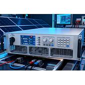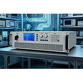
A bidirectional DC test power supply can validate an EV charger by both supplying DC energy and absorbing returned energy during controlled test cycles. This allows engineers to assess charger behavior across efficiency, voltage/current accuracy, protection, dynamic-load, and compatibility test conditions.
For high-power charger work, the key distinction is regenerative operation: energy absorbed by the test system can be fed back to the grid rather than dissipated solely as heat. The available capabilities and ratings should always be matched to the specific equipment configuration and test plan.
Summary: Bidirectional operation combines a DC source with a regenerative load. It can support dynamic charging and V2G-style scenarios. Reported capabilities include battery simulation, 0–2250 V coverage, and parallel expansion for higher-power testing.
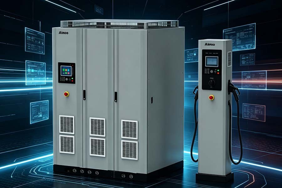
What is a bidirectional DC test power supply?
A bidirectional DC test power supply is test equipment that operates as both a DC source and a regenerative sink. In charger validation, it can provide energy to emulate a battery-side condition, then absorb energy when the device under test returns power.
This two-way energy flow is useful where a conventional one-way supply would convert returned energy into heat. The source material describes feedback efficiency of up to 92%–93% for the cited equipment, which can be relevant for long-duration, high-power test cycles.
Why is regenerative operation important for EV charger testing?
Regenerative operation is important because EV charger tests may involve sustained power transfer and, in bidirectional scenarios, returned energy. Feeding absorbed energy back to the grid can reduce the heat that a resistive load and its cooling arrangement must handle.
This approach can be particularly relevant to endurance or aging tests, where a charger operates for extended periods. It does not replace the need to define safe operating limits, protection settings, and site electrical requirements for each test setup.
Which charger parameters can a bidirectional test power supply help verify?
A bidirectional test platform can help verify conversion efficiency, output voltage and current behavior, protection response, and operation under changing loads. The following values are cited in the source as charger-test requirements or reported equipment capabilities.
| Test item or capability | Value stated in the source | Testing relevance |
|---|---|---|
| Charger output-voltage accuracy error | ≤ ±1% | Provides a benchmark for voltage verification |
| Charger output-current accuracy error | ≤ ±2% | Provides a benchmark for current verification |
| Rated-load charging efficiency | ≥ 95% | Supports efficiency measurement at rated load |
| Protection action time | ≤ 100 ms | Applies to overcurrent, overvoltage, and short-circuit tests |
| Reported source voltage/current accuracy | ≤ 0.05% F.S. | Supports precise setpoint control during testing |
A test supply with tighter control accuracy can help create a stable reference condition for assessing the charger. However, the charger’s compliance result depends on the complete method, instruments, connections, and applicable requirements—not on the power supply alone.
How can dynamic-load simulation reproduce EV charging conditions?
Dynamic-load simulation changes voltage, current, or power setpoints over time to represent transitions that occur during charging. Examples described in the source include constant-current to constant-voltage transitions, changes across battery state of charge, protocol changes, and reverse energy flow in V2G operation.
The cited bidirectional platform has a forward/reverse switching time of less than 1 ms, transient response of ≤2 ms, up to 900 programming steps, and a minimum programming time of 1 ms. These figures indicate the type of time-varying profile the equipment is intended to reproduce.
When is battery simulation useful instead of using a real battery pack?
Battery simulation is useful when a laboratory needs repeatable battery-output characteristics without relying on a physical battery pack. The source describes support for lithium, nickel-metal hydride, and lead-acid battery types, as well as first-, second-, and third-order battery models.
Battery parameter files in .mat or .csv format can be used to reproduce defined output curves. This can help teams compare charger behavior across selected battery characteristics while avoiding the handling and variability of multiple real battery packs.
What voltage and power range is described for high-voltage charger testing?
The source describes a 0–2250 V voltage coverage range with seven voltage-level options, intended to address testing from 400 V chargers through 800 V and 1000 V charging systems. This range is relevant as EV platforms move toward higher-voltage architectures.
For higher-power work, the source states that multiple units can be connected in parallel to expand capacity from 50 kW to 1 MW. Whether a particular configuration is appropriate depends on the selected units, parallel arrangement, and the charger’s required test current and voltage.
How should a team select a bidirectional DC test power supply for charger validation?
Select a bidirectional DC test power source
by first defining the charger’s voltage, power, current, operating modes, and transient profile requirements. Then confirm whether the test system needs regenerative operation, programmable sequences, battery simulation, and automated-test communication.
The cited platform lists CAN, RS232/RS485, and LAN interfaces, plus over-temperature, over-voltage, over-current, and over-power protection. These features can help integrate the power supply into an automated test environment, but the final selection should be based on the documented configuration needed for the intended test procedure.