When a solar panel reports a drop in output while the rest of the array appears to operate normally, where is the underlying fault? The answer is typically revealed when field engineers measure two fundamental parameters: open-circuit voltage (Voc) and short-circuit current (Isc). These two measurements isolate faults within the panel itself, wiring issues, or charge controller defects without needing to disconnect the entire string from the system. This article dives straight into the engineering-standard testing procedure and how to interpret results accurately to eliminate guesswork during troubleshooting.
What Do Voc and Isc Reveal That Output Power Measurements Cannot Detect?
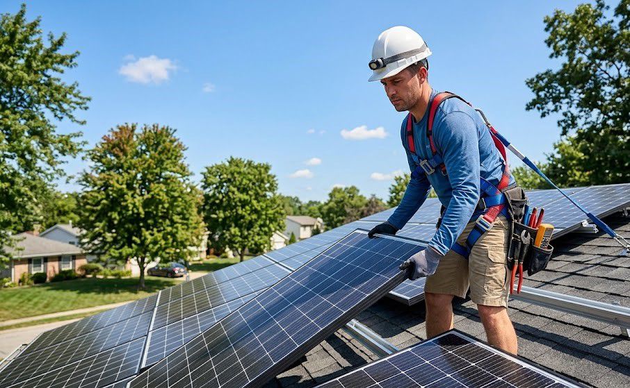
AC power measured downstream of the inverter is affected by cumulative variables: conversion efficiency, cable line losses, tilt angle, and partial shading across the array. Direct Voc and Isc measurements on individual panels isolate these external variables, providing isolated performance metrics for the tested module. This makes the procedure essential for pinpointing defective panels within strings containing dozens of units, bypassing time-consuming trial-and-error checks across every connection point.
3 Mandatory Prerequisites Before Connecting Meter Probes
1. Perform testing during peak sunlight hours, typically between 10:00 AM and 2:00 PM, when solar irradiance approaches the module's rated design specifications. Overcast conditions cause readings to drop significantly, failing to reflect true panel health.
2. Disconnect the solar panel from grid-tied systems or charge controllers prior to probe contact; never perform measurements while the panel remains actively connected. Electric arcing under active loads poses severe safety hazards compared to isolated testing.
3. Turn the multimeter dial to DC Voltage or DC Current depending on the required test, selecting a measurement range higher than expected thresholds to prevent blown fuses on initial contact.
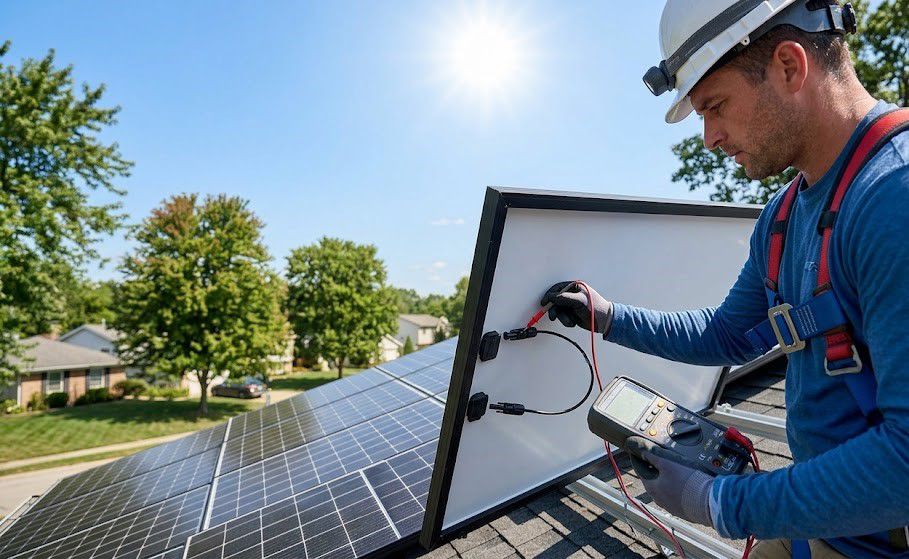
Measuring Open-Circuit Voltage (Voc): Simple Steps and Tolerance Analysis
Open-circuit voltage is the maximum voltage generated by a solar panel when no load is connected. Insert the red probe into the V terminal and the black probe into COM, then set the DC voltage range higher than the expected voltage—typically between 100V and 1000V DC depending on string configurations. Touch the red probe to the positive terminal and the black probe to the negative terminal; the reading displayed on the screen indicates the actual measured Voc.
To execute this step with high precision, field engineers can utilize high-end Fluke multimeters such as the Fluke 87V - MAX or Fluke 179, which offer CAT III 1000V safety ratings and stable DC voltage measurement capabilities.
A frequently overlooked step involves tolerance verification. Novice engineers often only check if the measured value roughly matches the nameplate rating, forgetting that acceptable error margins typically fluctuate within +/- 5%. Readings within this range are considered normal operating behavior, not indicators of hardware failure.
Measuring Short-Circuit Current (Isc): Preventing Multimeter Fuse Damage
Short-circuit current represents the maximum current produced when shorting the panel terminals. Because this contact generates a small electrical arc, probe placement must be swift and decisive without prolonged contact. Switch the dial to DC current, move the red lead to the high-current port (10A or 20A depending on meter specifications), press the red probe firmly to the positive terminal and black to negative, and record the displayed current instantly upon contact.
A major operational risk involves standard multimeter current limits. Solar panels rated above 200W frequently yield Isc values exceeding 10A, which standard handheld multimeters cannot handle without blowing internal fuses almost instantly. In such cases, technicians must switch to specialized DC clamp meters like the Fluke 393 FC (designed for solar systems up to 1500V DC) to measure current directly around conductors without direct probe contact.
Interpreting Test Results: Distinguishing Surface Dirt from Internal Cell Failures
+ Both Voc and Isc Meet Nominal Ratings: The panel is healthy and suitable for new installations or continued operation.
+ Normal Voc, Significantly Low Isc: Indicates surface dirt accumulation, partial shading, or degraded internal photovoltaic cells. Clean the module surface and verify surrounding obstructions before concluding hardware failure.
+ Voc Equals 0 or Drops Drastically: Indicates open internal circuits, junction box failure, or defective bypass diodes. Inspect the module backside thoroughly and replace damaged components upon detection.
Measuring High-Voltage Series Strings: Critical Safety Boundaries
Minor arcing during single-panel Isc measurement is normal, provided probe contact is brief and decisive. However, measuring multi-panel series strings presents far higher risks, as cumulative voltages can reach hundreds of volts. Never attempt to measure short-circuit current on an entire high-voltage string using standard multimeters. Such voltage levels pose severe life-threatening hazards and can destroy measurement tools instantly.
Mastering Voc and Isc measurement procedures allows field engineers to isolate faults rapidly, avoiding the need to dismantle entire strings to locate a single defective panel. To gain hands-on experience with 1500V DC solar testing instruments alongside technical experts, EMIN is collaborating with Fluke to host a seminar series on M&E and Solar Infrastructure Maintenance in Da Nang on October 27, 2026, and in Southern Vietnam on October 30, 2026. Register early to secure your spot, receive international-standard technical documentation, and test live equipment directly at the event.