The initial reaction is often to suspect motor failure or electrical issues. However, the control panel only provides necessary baseline conditions. The underlying causes of sample failure stem from mechanical and fluid-dynamic factors inside the chamber that the digital display cannot detect or signal.

1. Incorrect Adapter Cushioning and Tube Material Limits Causing High-Speed Shattering
It is a common misconception that test tubes withstand force uniformly under all conditions. At high speeds ranging from 15,000 to over 30,000 RPM, peak centrifugal acceleration subjects the tube bottom to immense hydrostatic pressure.
Placing conical-bottom tubes directly into round-bottom rotor cavities without specialized adapters concentrates all stress onto a single point, causing internal stress fractures or bottom breakage.
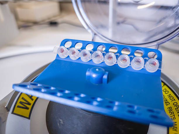
Polypropylene (PP) plastic loses structural integrity when exposed to aggressive organic solvents like chloroform or phenol, weakening polymer bonds and causing spontaneous failure under high centrifugal force.

Tubes designated for high-speed centrifugation have a finite operational lifespan. Repeated autoclaving or multiple high-speed centrifugation cycles induce micro-cracks in the plastic structure that are invisible to the naked eye.

- Verify geometric compatibility between the tube bottom and the rotor cavity prior to operation.
- Adhere strictly to balancing rules: Weight differential between opposing tubes must not exceed 0.1 grams; always use a precision balance for calibration rather than visual estimation.
- Fill tubes to a maximum of 2/3 capacity to prevent hydrodynamic pressure from popping caps or breaking tubes.
- Never reuse tubes for runs exceeding 10,000 RPM if they have undergone multiple thermal cycles. When starting the unit, remain nearby to monitor equipment for 1 to 2 minutes until it reaches stable operational speed (approximately 90% of rotor failures occur during the acceleration phase).
2. Aggressive Deceleration Settings Causing Remixing of Separated Layers
The deceleration phase represents the most critical window where separation interfaces are highly susceptible to disruption if parameters are improperly configured.
When decelerating rapidly from high speeds to 0 RPM, activating hard braking stops the rotor abruptly while the liquid column inside continues rotating due to inertia.
Velocity differentials generate micro-vortices and shear waves right at the phase boundary, resuspending freshly separated layers (such as the buffy coat layer in blood separation).
- For sensitive sample matrixes, configure deceleration parameters to "Soft Brake" or disable braking entirely ("No Brake" / Free Coasting) to allow the rotor to coast down naturally.
- Ensure the inner rotor lid is securely fastened before closing the main chamber lid.
3. Incorrect Rotor Geometry Selection Leading to Suboptimal Sample Sedimentation
Selecting an inappropriate rotor configuration prevents effective layer resolution or causes improper pellet adherence within the tube:
| Rotor Type | Mechanism & Sample Behavior | Recommendation / Mitigation |
|---|---|---|
| Fixed-Angle Rotor | Fixed tube angle from 25° to 45°. Force impinging against the outer tube wall creates a extended pellet smear along the wall. Upon deceleration, this smear easily slides down, clouding the liquid. | Ideal for supernatant collection. Do not use for density gradient separation or thin interface layer harvesting. |
| Swinging-Bucket Rotor | Buckets swing out 90° perpendicular to the axis of rotation. Sedimentation trajectory travels parallel along the tube axis, forming a tightly packed pellet at the bottom while preserving sharp boundary layers. | Gold standard for complex separations, density gradient centrifugation, and clean interface recovery. |
Explore our range of high-quality centrifuges distributed by EMIN
4. Emergency Response Protocol for Tube Breakage or Excessive Vibration
• Biohazardous samples: Wait a minimum of 30 minutes.