hether you are a skilled electrician, have worn out your hands with clamp meter, or just a personal user who wants to fix electricity in your home, "decoding" each function key on it is extremely important.
If you do not understand it clearly, you can measure incorrectly and cause the device to malfunction. No need to worry, this article will help you go from A to Z, thoroughly understand each parameter, each symbol to use the clamp meter most accurately and safely. Let's find out now!
Common symbols on clamp meters and their meanings
There are many types of clamp meters on the market today, each model integrates different measuring functions. To use correctly and effectively, you need to understand each symbol displayed on the device.
Some common symbols:
Ã: represents the alternating current (AC) scale when used with the clamp jaw.
V~: measures AC voltage.
V–: measures DC voltage. The hyphen is distinguished from the tilde (~).
Ω / 🔊 (speaker symbol or 3 curved lines): used for measuring resistance and checking continuity.
In addition to the basic symbols, clamp meters also have many other scales. Below are the functions commonly found on the display screen:
1. AC Voltage
2. AC and DC Voltage
3. 3–4. Millivolt
4. Capacitance
5. Resistance
6. Continuity Test
7. Temperature
8. DC Circuit
9. Frequency
10. AC Current Measured with Rogowski Coil (iFlex®)
11. AC/DC Current
12. DC Current
13. AC Current
Meaning of function keys on clamp meter
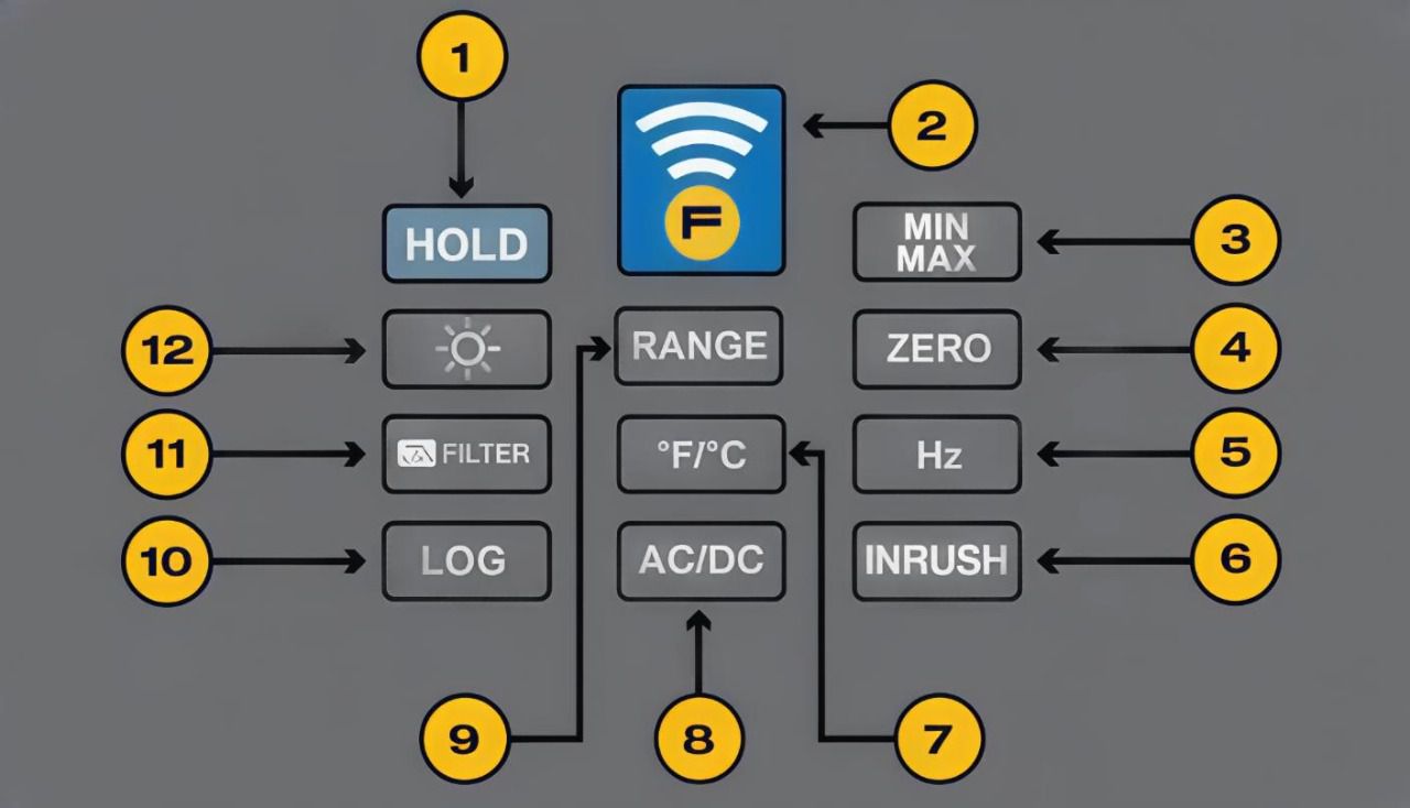
Clamp meters also have many function keys to support operations. Each model may be different, but some common keys include:
- Hold: keep the measurement result on the screen.
- Min/Max/Avg: display the minimum, maximum and average values.
- Zero: remove the DC component when measuring DC current.
- Inrush: measure and calculate the starting current.
- OFF: turn off the device.
- Backlight: turn on/off the screen's backlight.
Meaning of symbols displayed on the screen
On the clamp meter display, symbols help the user identify which measurement the device is performing. Typically there will be:
- Input current
- Temperature
- Hold mode
- Voltage (V)
- Current (A)
- Measuring units: capacitance, resistance, Ω and kΩ, AC/DC, frequency (Hz)
- Counting function
- Low battery indicator (for both remote and main unit)
- Clamp measurement symbol
- RF signal transmitted to remote display
- Continuity test
- Dangerous voltage warning
- Flexible probe measurement
- Min/Max/Average result display
- Min/Max mode active indication
With common clamp meters, the symbols for AC current (A~), hold function, and min/max values are clearly displayed on the front of the device. The function knob separates each measurement range, making it easy for users to identify the mode being used without having to memorize too many steps.
Refer to related articles about clamp meter to understand more about the product:
Notes when using clamp meter
In many previous articles, EMIN has shared many important notes when using a clamp meter. However, these are the basic points that you should definitely not ignore to ensure accurate and safe measurements:
- Choose the correct measurement mode for the current or parameter to be tested.
- Set the measurement range to match the expected value to avoid errors or the machine cannot measure.
- Check and reset the zero value when necessary, helping to eliminate basic errors.
- Make sure to choose the correct measurement unit (V, A, Ω…) to read the results accurately.
- Use the Hold function when you need to keep the measurement result on the display.
- After measuring, compare the result with the specifications or expected value.
- Always follow the manufacturer's instructions, especially when using new features.
Conclude:
Above is an explanation of the common function keys on clamp meters. Hopefully this information will help you operate more easily and exploit the device effectively. If you need further advice on how to choose or use clamp meters, you can contact EMIN directly via hotline for support.