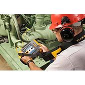
The same cable route and the same equipment can produce different measurement results after each reconnection. This is often related to the stability of the connectors, test leads, or the reference setup procedure. Repeatability should be checked by taking multiple measurements with the same configuration before evaluating the quality of the link.
What Does Optical Fiber Loss Measurement Indicate ?
Optical fiber attenuation refers to the reduction in light power as the signal travels from the transmitting end to the receiving end. This value is typically expressed in decibels (dB) and is present in every fiber transmission link.
In addition to a fiber optic cable loss tester, Optical power meter together with an optical light source to determine link loss and evaluate transmission performance.
Abnormally High Measurement Results Caused by Improper Connector Handling
Fiber optic connectors have extremely small contact surfaces. Even a thin layer of dust or fingerprints that are barely visible to the naked eye can scatter light and introduce additional attenuation. As a result, measurement values may vary between test cycles even when the network itself is operating normally.
A good practice is to clean the connector before every connection, including when fiber optic test equipment has just been removed from its protective case.
Selecting a Wavelength That Does Not Match the Link Design
A fiber optic link may produce different attenuation values depending on the test wavelength.
During acceptance testing, the wavelength should be agreed upon in advance and clearly documented in the technical report to ensure all teams interpret the results using the same criteria.
For example, measuring at 1310 nm while comparing the results against design specifications defined at 1550 nm can lead to incorrect conclusions. Likewise, using a multimode test configuration to evaluate a singlemode link reduces the reliability of the measurement data.
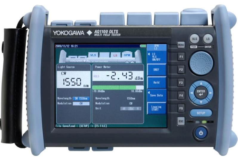
Skipping Reference Setup Causes Systematic Measurement Errors
Technicians sometimes replace test cords or move to another link while keeping the previous reference settings unchanged. This can introduce cumulative errors across all subsequent attenuation readings.
This is one reason why the same fiber link may produce different results when retested with another instrument under identical conditions.
Resetting the reference level before each measurement cycle only takes a few extra minutes but significantly improves data consistency and long-term comparability.
Test Accessories Can Influence Measurement Results
In optical measurement systems, patch cords and adapters are more than simple connection accessories.
A worn or degraded connector may introduce more attenuation than the section of cable being tested, making it easy to misidentify the source of the problem.
If measurement values fluctuate unexpectedly between repeated tests, the reference cord set should be verified before drawing conclusions about the network condition.
The cable passed acceptance testing but attenuation increased over time
If the measurement result is higher after a period of operation than the original acceptance data, the installation condition should also be checked.
Fiber optic cables installed inside cabinets, optical distribution boxes, or cable trays may become sharply bent, compressed, or stretched during operation. These changes can increase attenuation at a specific location.
Comparing the current OTDR trace with the initial measurement data can help identify where changes have occurred. If the attenuation has increased at the same point, the corresponding cable section and connectors should be inspected directly.
Evaluating a Fiber Link Based Only on Attenuation Values
Long-distance links, networks with multiple splice points, or installations operating under demanding environmental conditions behave differently from standard configurations.
Measurement results become meaningful only when reviewed alongside the original design data, operating conditions, and maintenance history. Trend analysis over time often provides a more reliable assessment than a single standalone measurement.
Measurement accuracy does not depend solely on the optical loss tester. Preparation, measurement procedures, and testing conditions play equally important roles. Small deviations related to connectors, wavelength selection, accessories, or instrument configuration can all lead to incorrect assessments of link quality.
Establishing a standardized measurement procedure, performing routine inspections, and selecting suitable optical power tester will improve data reliability and support more effective acceptance testing and system maintenance.