DIFFERENTIAL PRESSURE METERS FOR AHUs, FCUs, AND AIR DUCT SYSTEMS
In an HVAC system, air does not move across different zones with the exact same pressure level. When passing through filters, coils, fans, or duct sections with varying resistance, the airflow pressure changes accordingly. Measuring the pressure difference between two specific points thus reveals vital information about system status that is otherwise invisible to the naked eye.
What Differential Pressure Meters Measure in HVAC Systems
Unlike standard pressure gauges that measure pressure at a single point relative to a reference benchmark, a differential pressure meter determines the exact difference between two separate pressure inputs.
For example, to inspect an air filter inside an AHU, a technician can take pressure readings upstream (before) and downstream (after) the filter. The meter then displays the differential pressure across both sides. The higher the resistance encountered by the air passing through the filter, the greater the pressure difference between the two points.
This measurement method is particularly valuable in HVAC engineering because many system issues cannot be diagnosed simply by looking at an isolated pressure value. The primary metric of interest is usually how much pressure changes as airflow passes through a specific component or between two zones. A brand-new filter creates a specific initial differential pressure; over time, accumulated dust increases resistance, altering the differential pressure. By tracking the exact same location over multiple inspections, technicians gain a solid baseline to evaluate system performance trends.

Why AHUs Require Differential Pressure Measurement Across Filters
Air filters represent one of the most obvious applications where differential pressure measurement proves its value. For air to pass through a filter, it must overcome the physical structure of the filter media. As trapped dust accumulates, resistance to the airflow increases correspondingly. Looking at the filter externally makes it nearly impossible to determine how severely dust buildup is affecting air movement. Measuring differential pressure across both sides of the filter provides a direct quantitative indicator of that operational change.
Importantly, a single arbitrary differential pressure threshold should not be applied universally across all filters. Every filter grade, airflow rate, AHU configuration, and operating requirement can yield different differential pressure figures. Measured values must always be cross-referenced against manufacturer specifications or baseline system operating parameters. Therefore, the most effective way to use a differential pressure meter is not to take a single reading and jump to conclusions, but rather to log the differential pressure when the filter is newly installed and track it continuously over time. Trend data holds far greater diagnostic value than a standalone static number.
Read more: When do engineers need to use a differential pressure meter instead of a standard mechanical gauge?
Comparing Applications: AHU, FCU, and Ductwork Systems
While the underlying measurement principle remains identical, pressure tapping locations and primary inspection goals differ noticeably depending on the application:
| Application | Common Pressure Tapping Points | Primary Inspection Purpose |
|---|---|---|
| AHU | Upstream and downstream of filters; across cooling/heating coils | Evaluating filter resistance; tracking dust accumulation over time |
| FCU | Upstream and downstream of filters; specific duct locations near fans or coils | Checking filter resistance or localized duct pressure in small-scale HVAC setups |
| Ductwork System | Upstream and downstream of elbows, bends, dampers, diffusers, or test components | Determining pressure loss along duct runs; measuring pressure drop across individual components |
With FCUs—which operate on a smaller scale than AHUs and are usually installed directly within conditioned zones—it is crucial to define exactly which component is being tested and where the two measurement points are located. Placing sensing probes incorrectly will still produce a numerical readout, but it will fail to reflect the actual parameter being evaluated. This is precisely why HVAC differential pressure meters come with flexible sampling tubes, allowing pressure signals from hard-to-reach locations to be routed back to the meter's dual input ports without placing the device body inside the ductwork.

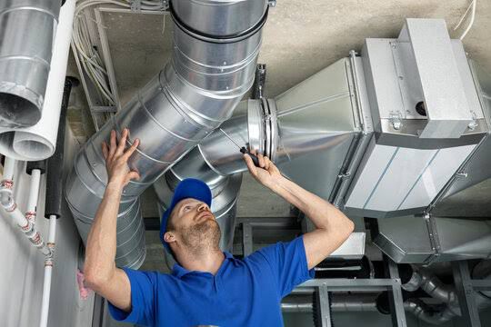
In ductwork systems, pressure fluctuates based on location, duct dimensions, airflow rate, and inline components. Bends, elbows, dampers, filters, and supply diffusers all introduce pressure drops. Consequently, tapping point selection is just as critical as the accuracy of the meter itself; the two test points must align strictly with the testing objective. If sampling locations shift between test routines, comparing historical results loses validity.
The Relationship Between Differential Pressure and Airflow Rate Measurement
This is an area that frequently leads to confusion when selecting instrumentation. A differential pressure meter does not automatically function as an airflow volumetric meter simply by connecting it to a duct. However, when paired with a Pitot tube, the measurement leverages the pressure differential related to fluid dynamics (velocity pressure) to determine air velocity. Combined with the duct cross-sectional area and appropriate calculation formulas, the volumetric airflow rate can be accurately derived.

The measurement chain follows this sequential logic:
When connected, a Pitot tube uses dedicated pressure ports to capture total pressure and static pressure from the moving airstream. These two pressure signals are fed into the meter's two ports, which then calculates the differential (velocity pressure). When measuring duct velocity, probe placement and sampling methodology directly dictate accuracy. Real-world duct airflow is rarely uniform across the entire cross-section, particularly near elbows, dampers, or turbulent zones. Choosing proper measurement planes, traverse point numbers, and sampling methods must follow standard duct traverse protocols and system geometry.
| Job Requirement | Recommended Measurement Equipment |
|---|---|
| Simple filter differential pressure checks | Basic differential pressure meter (flow calculation functions not required) |
| Ductwork survey requiring air velocity or flow rate | Advanced model supporting Pitot tube connection and automatic velocity/flow calculation |
Is Increased Differential Pressure Always a Sign of a Dirty Filter?
Not necessarily. Assuming a high pressure drop automatically means a dirty filter is a common misconception when interpreting test results.
Differential pressure fluctuations can stem from several operational variables. While dust buildup on filter media is a primary cause, changes in total system airflow rate, fan speed adjustments, or altered damper positions also cause differential pressure values to shift. For instance, if system fan speed increases and drives up velocity, the pressure drop across various system components increases inherently. Observing a higher differential pressure in this scenario is insufficient evidence to conclude that the filter requires replacement.
A sound diagnostic approach requires evaluating test results within the context of actual operating conditions, comparing readings against original design specs, manufacturer curves, or historical trend data. The meter supplies raw pressure data; accurate interpretation requires an understanding of overall system dynamics.
Key Selection Criteria for HVAC Differential Pressure Meters
| Criteria | Key Considerations |
|---|---|
| Measuring Range | Select a device range matched to typical HVAC operating pressure zones rather than choosing an excessively high-range model that compromises low-end resolution. |
| Display Units | Ensure compatibility with technical documentation; standard units include Pa, kPa, mbar, and inH₂O. On-device unit conversion simplifies cross-referencing multiple engineering standards. |
| Pressure Port Connection Type | Verify compatibility with flexible tubing adapters if routinely testing filters or duct ports. |
| Velocity and Airflow Functions | Essential only if duct velocity or volumetric flow surveys are required; ensure native Pitot tube calculation support. |
| Data Logging, Max/Min Hold, and Connectivity | Highly useful for routine preventive maintenance; essential when testing protocols demand trend tracking and digital record-keeping. |
Determining the Right Differential Pressure Meter for Your HVAC Workflow
Across AHUs, FCUs, and extensive air duct networks, the common denominator is the need to quantify pressure changes between two distinct points.
- In AHUs, measurements focus on evaluating filter resistance and pressure drops across cooling or heating coils.
- In FCUs, meters inspect localized filter resistance and static pressure across compact duct runs.
- In Ductwork Systems, measurements verify pressure loss across components or pair with Pitot tubes for comprehensive flow surveys.
Therefore, equipment selection should not begin with asking "which model has the most features," but rather "what parameter needs measuring, at which location, and under what operating conditions." Once these three parameters are defined, selecting the right measuring range, connection ports, and auxiliary features becomes straightforward.
In HVAC testing, a number on a display screen is only meaningful when the technician knows exactly where the sample was taken, under what system conditions, and what physical property it represents. That is why differential pressure meters are paired with sampling tubes, Pitot tubes, and specialized accessories across AHU, FCU, and ductwork maintenance. Selecting the proper meter is only step one; establishing correct measurement points and accurately interpreting differential pressure data is what ultimately drives effective HVAC maintenance and performance optimization.